29
Linea
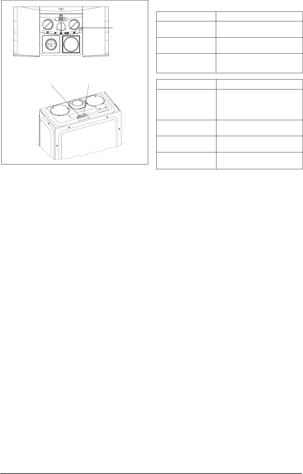
Fig. 43
7.4 COMBUSTION ANALYSIS TEST
A combustion analysis check can easily be car-
ried out on the appliance via the test points lo-
cated on the top of the appliance, however you
must check that the burner pressures are set cor-
rectly (see 7.3).
●●
●●
● Insert the flue gas analyser probe into the right
hand test point (see fig 43).
●●
●●
● Locate and remove the protective cap that con-
ceals the ‘CO mode’ button (see fig. 43).
●●
●●
● Light the boiler as described in 5.7 and press
the ‘CO mode’ button once.
●●
●●
● The boiler will now enter the combustion analy-
sis mode (CO mode) for a period of 15 min-
utes. During this time it will remain on full gas
and ‘CO’ will be displayed on the LED display.
●●
●●
● Once the flue gas analysis has been made,
press the ‘CO mode’ to resume normal opera-
tion.
7.5 CHECKING THE EXPANSION VESSEL
Carry out the component removal procedure as
described in 6.4. You must ensure that the boiler
is completely drained of water.
Using a suitable pressure gauge, remove dust
cap on expansion vessel and check the charge
pressure. The correct charge pressure should be
1.0 bar ± 0.1 bar.
If the charge pressure is less, use a suitable pump
to increase the charge.
NOTE
You must ensure the safety valve is in the open
position whilst re-charging takes place. Replace
the dust cap and carry out the relevant commis-
sioning procedure (section 5).
7.6 EXTERNAL FAULTS
Before carrying out any faultfinding or component
replacement, ensure the fault is not attributable
to any aspect of the installation.
7.6.1 INSTALLATION FAULTS
Symptom Possible causes
No ignition Check wiring
Check electrical supply
No hot water Check hot/cold pipe
work is not reversed
No central heating Check wiring of time clock
and/or room thermostat
Fault code Possible causes
01 Gas supply problem
Gas line requires purging
Reversed polarity
Broken, internal flue joint
02 Flow/return valves closed
Stuck pump
03 Debris in flue system
Debris in flue venturi
04 Insufficient water pressure
Air in boiler
7.7 ELECTRICAL CHECKS
Any electrical checks must be carried out by a
suitably qualified person.
7.7.1 EARTH CONTINUITY TEST
Isolate the appliance from the electrical supply,
and using a suitable multi-meter carry out a re-
sistance test. Connect test leads between an
appliance earth point and the earth wire of the
appliance supply cable. The resistance should
be less than 1 OHM. If the resistance is greater
than 1 OHM check all earth wires and connec-
tors for continuity and integrity.
7.7.2 SHORT CIRCUIT CHECK
Isolate the appliance from the electrical supply,
and using a suitable multi-meter, carry out a short
circuit test between the Live & Neutral connec-
tions at the appliance terminal strip (fig.16).
Repeat above test on the Live & Earth connec-
tions at the appliance terminal strip (fig.16).
NOTE
Should it be found that the fuse has failed but no
fault is indicated, a detailed continuity
Check will be required to trace the fault. A visual
inspection of components may also assist in lo-
cating the fault.
7.7.3 POLARITY CHECK
With the appliance connected to the electrical
supply and using a suitable multimeter, carry out
the following voltage tests:
Connect test leads between the Live & Neutral
connections at the appliance terminal strip
(fig.16). The meter should read approximately
230V ac. If so proceed to next stage. If not, see
7.7.4.
Connect test leads between the Live & Earth con-
nections at the appliance terminal strip (fig.16).
The meter should read approximately 230V ac.
Protecting
cap
Air analysis outlet Fumes analysis outlet
 (40 pages)
 Manymanuals.com
 Manymanuals.de
 Manymanuals.fr
 Manymanuals.it
 Manymanuals.pl
 Manymanuals.cz
 Manymanuals.es
 Manymanuals-pt.com
Comments to this Manuals